No Longer Available - For Reference Purposes Only
No Longer Available - For Reference Purposes Only |
RWT-3820 & RWR-3820:
'L' Band FM RF Fibre Optic Link. | ||
USES:
|
||
FIBRE OPTIC LINK BENEFITS INCLUDE:
|
||
GENERAL:
|
||
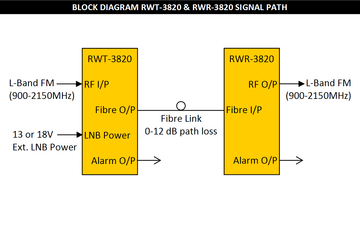
The IRT RWT-3820 / RWR-3820 Wide Band RF Fibre Optic Link is a modular system for transmitting broadband
RF 'L' band FM modulated signals over an optical fibre cable. The system response is from 900 - 2150 MHz. | ||
|
||
TECHNICAL SPECIFICATIONS:
|
||
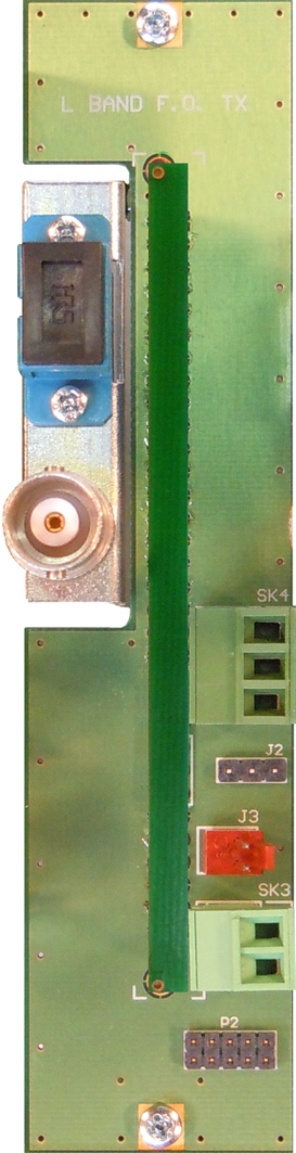
RWT-3820: |
|
RF signal connection |
75Ω SMC on module rear panel. (BNC and F adapters provided). |
RF Monitor connection |
BNC connectors front panels (allows easy setting up of RF levels). |
RF input level |
Adjustable in the range -40 dBm to -20 dBm total power. |
LNB power supply |
13 or 18V input to rear panel, SK3, can be applied. |
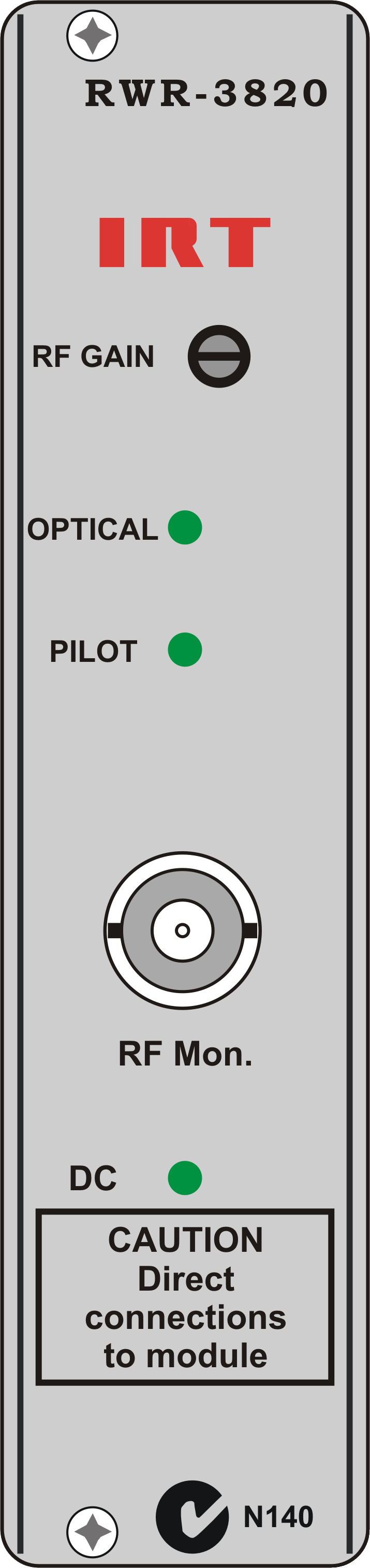
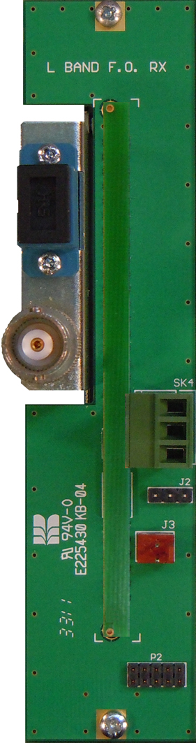
RWR-3820: |
|
RF signal connection |
75Ω SMC on module rear panel. (BNC and F adapters provided). |
RF Monitor connection |
BNC connectors front panels (allows easy setting up of RF levels). |
RF output level |
Adjustable in the range -45 dBm to -20 dBm total power. |
Performance: |
|
Input / output VSWR |
< 2: 1 (75Ω). |
System frequency response |
900MHz to 2150 MHz operation. |
500 MHz flatness |
± 1.5 dB. |
36 MHz flatness |
± 0.5 dB. |
System group delay: |
±2 ns 900 MHz - 2150 MHz |
Carrier to noise |
> 26 dB for 36 MHz bandwidth. |
Intermodulation products |
< 40 dBc. |
Optical: |
|
RWT-3820 optical output power |
0 dBm. |
RWR-3820 optical input power |
-5 dBm to -15 dBm. |
(Note: 10 dB pad provided for back to back operation where path attenuation is less than 5 dB). |
|
System optical budget |
12 dB. |
Optical signal connections |
SC/PC (accessible from the rear of the module) for use with single mode (9/125 µm) fibre cable. |
Power Requirements: |
|
Voltage |
28 Vac CT (14-0-14) or ±16 Vdc. |
Power consumption |
6 VA for RWT-3820 and 5 VA for RWR-3820. |
Other: |
|
Temperature range |
0 - 50°C ambient. |
Mechanical |
Suitable for mounting in IRT 19" rack chassis with optical, RF & alarm connections at the rear. |
Finish: Front panel |
Grey background, black lettering & red IRT logo. |
Rear assembly |
Detachable silk-screened PCB with direct mount connectors to Eurocard and external signals. |
Dimensions |
6 HP x 3 U x 220 mm IRT Eurocard. |
NOTE: |
All the parameters specified are only applicable when using single mode (9/125 µm) fibre cable with a return loss of ≥27 dB. |

|
Due to our policy of continuing development, these specifications are subject to change without notice.
|